The TSL-3 tester is used to diagnose the most common zirconium lambda probes. It also allows you to simulate a rich or lean mixture.
To test the lambda probe, first locate the signal wire of the lambda probe (preferably using the diagram) and connect to it (in parallel – according to the drawing ), for example, using a pin probe or the pin itself, the blue wire of the TSL-3 tester. The black wire of the tester should be connected to the second pole of the lambda probe – most often this is its housing and the “ground” of the car, but there are probes that have a “negative” pole in the form of a wire. The signal of the lambda probe is weak and therefore it is important to keep the contact resistance as low as possible in order to make a correct measurement.
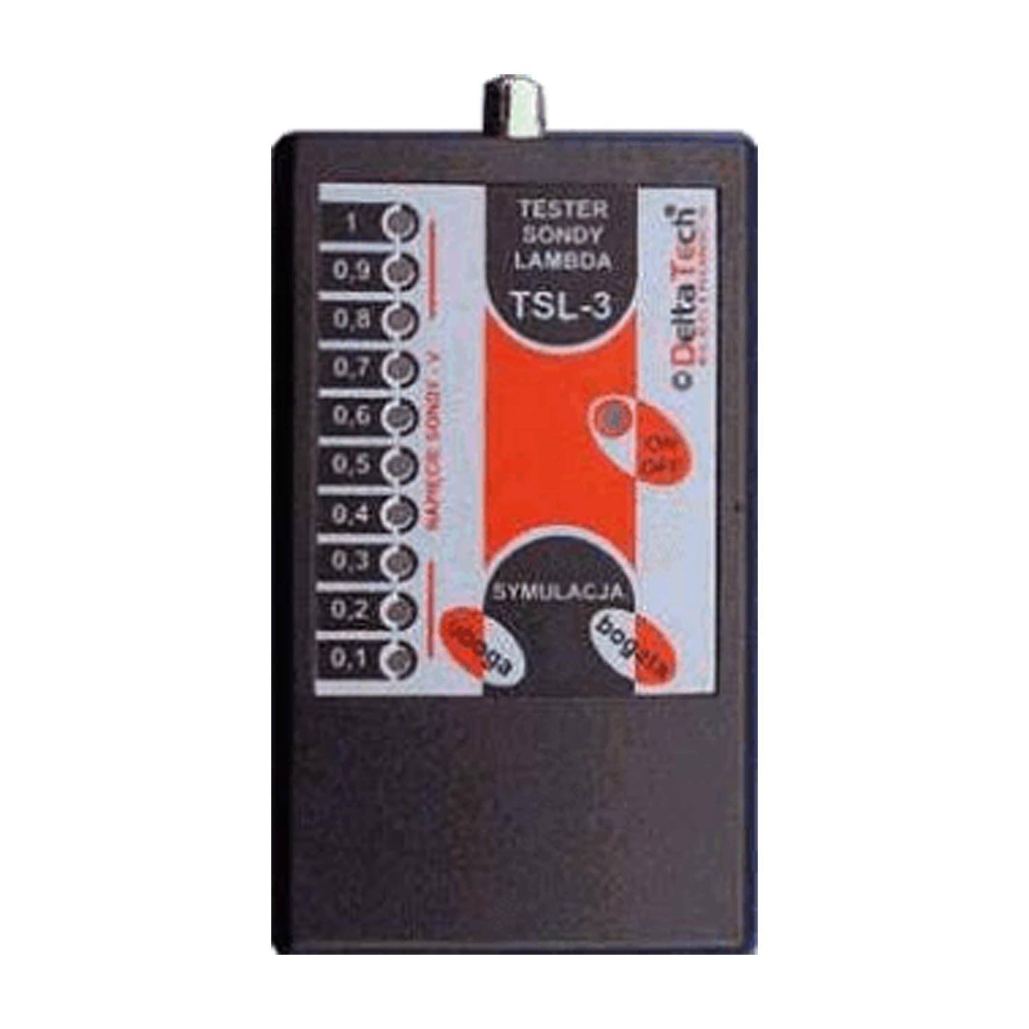
Then start the engine and after the lambda probe has warmed up (about 10 min at 1000 rpm) it should give a signal with an aplitude of about 0.8 V and a frequency of 1 Hz. The voltage indicator will then indicate a changing voltage from 0.1 V to 0.8 V and these changes should occur about once per second.
If the voltage does not exceed 0.5 volts or its changes are too slow, it means that the lambda probe is worn out and should be replaced.
Note, however, that any short circuit in the lambda probe circuit will result in a lack of signal from the probe even though the probe itself may still be in good condition. Therefore, if you detect a lack of signal from the lambda probe first check, it has a short circuit in its circuit, and only then decide to replace it.
In order to check the proper operation of the lambda probe circuit and the response to its signals of the control device (ECU), we can simulate a lean and rich mixture. If you have an exhaust gas analyzer, it will certainly prove helpful during this test. With the TSL-3 tester already connected, we can press the simulation button on it, for example. “poor mixture” and then in response to this signal the controller should enrich the mixture, which can be observed on the exhaust gas analyzer. If you do not have an analyzer, after releasing the “poor mixture” button , we should immediately observe the indication of the tester corresponding to the rich mixture.
We can similarly perform the same test by simulating a rich mixture. When the “rich mixture” button is pressed, the controller should deplete the mixture, which can be observed on the exhaust gas analyzer. In case you do not have an analyzer, you will observe a tester indication corresponding to a lean mixture.
During these tests, we can also measure the fuel injection time, which will change according to each situation.
It was assumed that the point separating the poor and rich mixture is a voltage of 0.45 V, corresponding to a lambda coefficient of 1. In practice, this means that readings on the tester from 0.1 to 0.4 V correspond to a poor mixture, while readings from 0.5 to 1 V correspond to a rich mixture.


