MENU
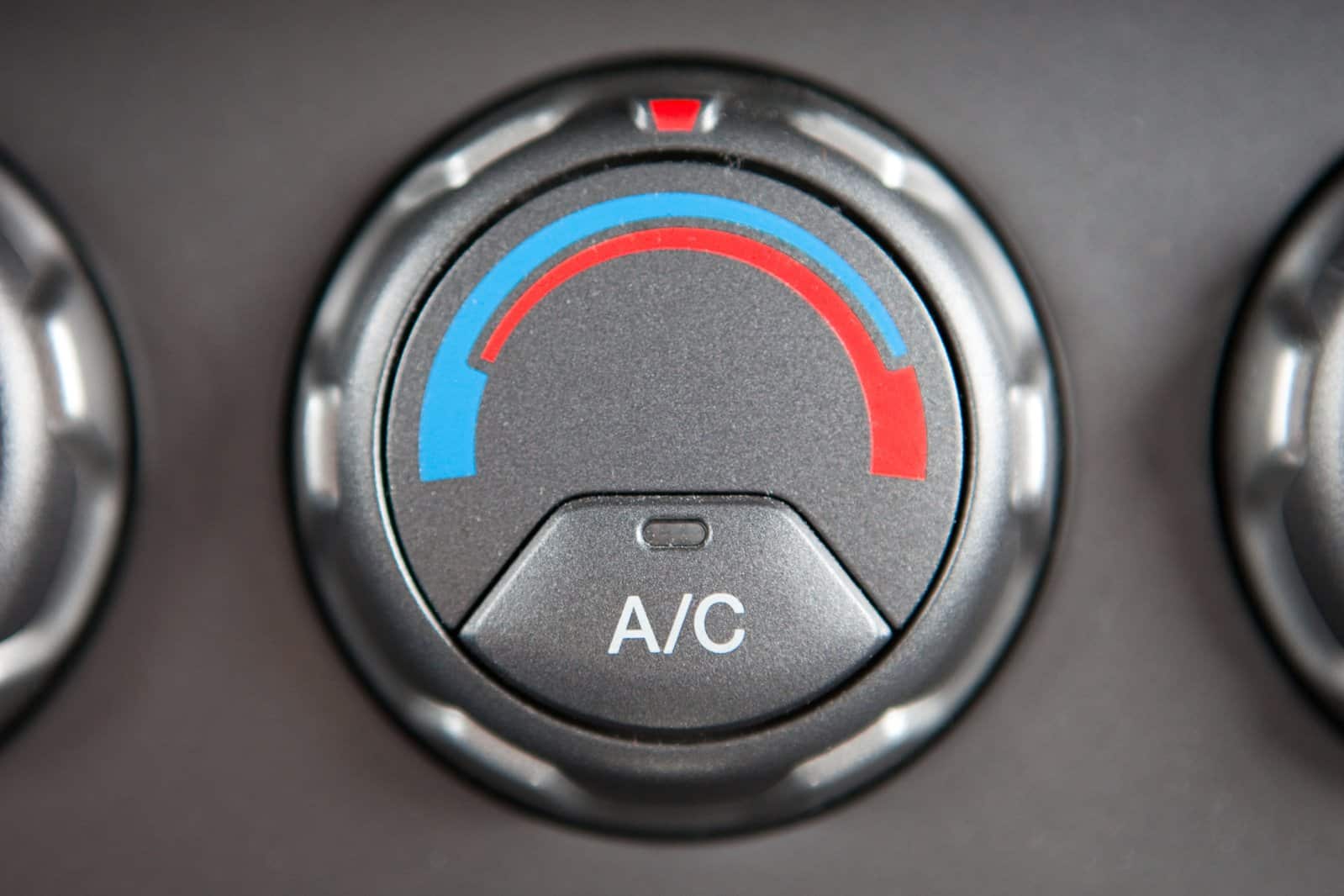
Spring is the time when motorists are traditionally reminded of the air conditioning system and the need to service it, especially when it appears that the system has refused to serve after winter. Below we will describe the basic criteria for A/C system diagnostics and show the tools available from DTE.
While this is obvious to many, it is worth recalling the basics of how the system works. Whether the service work is undertaken by young people with unestablished knowledge or practitioners with experience, it is much better to work with a system whose operation one understands to some degree. The air conditioning system is a heat pump that removes heat from the cooled interior of the vehicle to the outside. The ambient temperature may be higher than in the cabin. Since such a flow cannot occur on its own, it is necessary to use refrigerant and operate the compressor that makes it possible.
The air conditioning system in a car works similarly to a home refrigerator or air conditioner. An evaporator located in the cabin air supply system cools it down by boiling the refrigerant at reduced pressure. Condenser, allows the refrigerant to condense at a higher temperature due to the increased pressure provided by the compressor. Due to the power required, the compressor is not driven electrically (except in electric vehicles), but directly from the engine via a belt.
The air-conditioning system consists of many components with sometimes small flow light like the condenser, dehumidifier, expansion nozzle and expansion valve. These components are the most susceptible to clogging by filings or debris resulting from damage or corrosion.
When servicing air conditioning, it is worth using a consistent routine, starting with some simple tests that often do not require specialized equipment. The following is a simplified scheme that should work for various car models. First, start the engine and see if the air supply works, and if not, focus on the blower circuit – fuse, relay, blower resistors, motor.
If the air intake is working, it is usually assumed that an efficient air conditioning system provides air flow to the cabin of 2 – 8°C at an ambient temperature of at least 15°C. We assume a maximum cooling setting and a medium level of supply. If you find a lack of cooling after turning on the air conditioner, it is worth first assessing the air supply path: the cabin filter, the flaps of the supply nozzles, the heater valves. Next, we check whether the compressor clutch has been engaged or whether the variable compressor valve has been driven (using an oscilloscope or a tester, such as ACT-2). If the compressor is not switched on then it is a good idea to evaluate the power supply system and the wiring of the system (fuse, temperature sensor, electromagnetic clutch).
Even without the use of pressure gauges, we can make a subjective assessment of the system’s performance based on how the temperature feels. After at least a few minutes of idling the system under conditions as described in the previous paragraph, we proceed with the test. We keep the engine speed at 2,500 rpm for a minute and evaluate the heat of the wires. The line between the compressor and condenser (highest pressure) should be very hot, before the filter/drier warm, and before the compressor (low pressure side) noticeably cold.
If the air conditioning system does not work for a while, the readings of the high-pressure and low-pressure gauges should equalize after a while and be about. 5 bar at an ambient temperature of 20°C. Refrigerant loss is most often responsible for too low a pressure.
In the case of a properly operating air conditioning system (heated engine, engine speed 2500/min), the prevailing pressures on the low-pressure (LP) side ti1 – 3 bar (in the case of automatically regulated compressors it is 2 bar). High pressure should be between 9 – 25 bar (typically 13 – 17). If the results obtained are out of range then we should follow the service instructions of the respective vehicle manufacturer. Common causes of under-pressure include a lack of refrigerant, a dirty evaporator or a faulty compressor. Examples of causes of excessively high system pressure include a faulty condenser fan, system overflow, a dirty condenser or a defective expansion valve.
This type of compressor is distinguished by the fact that it is driven whenever the engine is running, which means that it should be maintained in proper condition even when not in use (including in winter). In such vehicles, special care should be taken to regularly check the condition of the air conditioning system, which should verify the amount of refrigerant. Keep in mind that by mixing it with oil, it forms the basis of compressor lubrication.
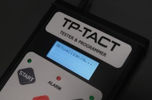
If we are observing the correct pressure gauge readings and the correct amount of refrigerant is present, but we cannot run the system in the normal way, we will need an external tool to set the valve. Such a tool is the ACT-2 tester. The device allows you to drive the valve by tasking the PWM value of the control signal and thus smoothly adjust the cooling capacity. This allows you to objectively assess the efficiency of the compressor by observing the response to the control signal. The device also has a measuring module to check whether the control signal is reaching the valve. Even without an oscilloscope, we can easily read the value of the fill factor generated by the controller along with its frequency. In addition, it gives the ability to fully imitate the control signal by adjusting the signal frequency.
If the compressor clutch is present, diagnostics of the air conditioning system can be carried out at a convenient time – if the system is not engaged then the compressor remains stationary. This is important in case of loss of leakage and refrigerant leakage – by refraining from operation, the user can protect the compressor from seizure. In such a system, the compressor clutch is either engaged or disengaged, so the control is simpler. Of course, in such a case, the ACT-2 is also useful – it will conveniently allow you to test the presence of the control signal in the car, and also allow you to independently force the system to work by driving the compressor clutch.
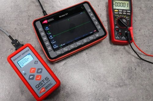
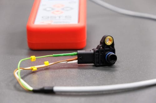
An interesting addition to the capabilities of an A/C service workshop is the QST-5 sensor tester. It is a universal device that allows independent testing of multiple sensors in vehicles. In air conditioning systems, it can help assess the performance of pressure or temperature sensors. These are small, but important components of the system, the checking of which also outside the vehicle facilitates diagnostics. The big advantage of the tester is that there is no required knowledge of the sensor leads – in typical cases the sensor will recognize the sensor lead layout on its own. The tester requires that the component under test be disconnected from the vehicle’s installation.
These sensors convert the measured pressure value into a proportional output voltage. The typical measurement range of such a sensor is approx. 30 bar, and the output voltage range can be 0.25 – 4.75 V. Examples of sensors of this type: 09131721 (Opel), 51768498 (Fiat). By observing the voltage readings and applying test pressure to the sensor, we can check if it is operational.
The second variant of the sensor generates an output signal with a fixed frequency and a variable signal fill factor. An example of such a sensor is the G65 element used by VW group vehicles. (Sample part numbers: 1K0959126E, 1J0959126, 8E0959126).
Many, especially older vehicles, used air-conditioning pressure sensors in the form of switches usually signaling minimum and maximum pressure independently. The test of such a sensor with the QST-5 is possible only after selecting the “Two-state” option from the list of sensors. In this situation, automatic detection is possible only if the contact is in the closed position. If the contact is in the open position at the start of the test, use the test in manual mode.
Temperature sensors are usually NTC (Negative Temperature Coeficient) thermistors in which the resistance decreases with increasing temperature. Thermistors with very different resistance-temperature dependencies are being produced. The QST-5 tester allows continuous measurement of sensor resistance, and has several typical temperature scales for conversion.







DeltaTech Electronics to polski producent i ekspert w branży automotive, który na bazie ponad 25 lat doświadczenia wyznacza trendy w innowacyjnej diagnostyce samochodowej.
To, co nadaje rytm naszej pracy, to wsłuchiwanie się w potrzeby klientów oraz śledzenie aktualnych problemów, z którymi mierzą się warsztaty samochodowe. Owocem tego jest oferta skrojona idealnie „na miarę” ich oczekiwań.
Cały cykl życia produktów od momentu projektowania rozwiązań, poprzez produkcję, kontrolę jakości i opiekę posprzedażową odbywa się w Firmie. Jakość tego procesu dokumentują liczne nagrody branżowe.
Naszą dumą jest szybkie wsparcie techniczne, polska jakość oraz setki zadowolonych klientów. Firma współpracuje z kluczowymi dystrybutorami w branży motoryzacyjnej.